|
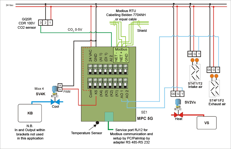
Temperature sensor GT1R placed in room controlling the sequence in the
following order to increase heating by room controller SE1.
-
Close the control valve SV4K gradually against KB refrigeration
system to reduce cooling media.
-
Reduce the intake and the exhaust air gradually by closing the
damper actuator ST4T1 and ST4T2 for intake air respectively ST4F and
ST4F2 of exhaust air from their mechanically adjusted max level to
their mechanically adjusted min level to reduce resp. airflow.
-
Open
the control valve SV2Vx, gradually against VS heating system to
increase the heat media, to keep the setpoint SE1. By decreasing
heating demand the control function occurs in reverse order.
Setpoint 21°C ± 4°C
By outdoor temperature undercutting 5° C close the valve SV2Vx, only to
the adjusted minimum position.
This is to prevent cold air, which means that if the outdoor temperature
drops to below 5° C when the control valve is closed, open it to its
minimum position.
Minimum Position is adjustable and initially set it to 20 %.
The intake/exhaust air dampers can be override depending on air quality
in the room.
Forced ventilation obtained in the room at elevated CO2 levels recorded
by air quality sensors which means that intake air damper ST4T1 and
ST4T2 and exhaust air damper ST4F and ST4F2 open to their mechanically
matched max level and remains there as long as air quality sensors
register elevated CO2 concentration.
The intake and exhaust air damper close the dampers to the mode under
temperature control when the air quality sensor registers a lower CO2
content.
Setpoint START 1 000 ppm
Setpoint STOP 800 ppm |