|
INPUT/OUTPUT MODULES, FLOATING |
|
|
Tri State Input to Analogue Current or Voltage
Output
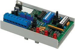
The FCV converts a floating point signal into a linear analog output.
There are two inputs on the FCV, one to increase
the analog output and one to decrease the analog output.
The output of the FCV is stable when the inputs
are both off.
A contact closure or voltage signal to either
input will cause the output of the FCV to begin to ramp either up or
down depending on which input was activated.
|

FCV
|
|
|
|
|
|
|
|
|
 |
 |
|
|
|
CE-cert. |
Datasheet |
|
|
|
|
The output stops ramping once the up or down
input is deactivated, and will remain at that value until another up or
down signal is received. If both inputs are "ON" the output will reset
to the lowest value of the selected range.
The output of the FCV is in the form of an
analog, steady state voltage or current.
This signal can be scaled to fit the needs of the
application by selecting 1 of several preset ranges by dip switch or by
adjusting the offset and the gain of the output with two potentiometers.
The output of the FCV is also protected against
wraparound. In the event the output reaches either its maximum or
minimum level, the ramping will stop and the output will be held at that
value.
The output signal rate of change is field
selectable by dip switch. Custom variations are available for rate of
change, reset, input and output configuration.
|
|
|
|
|
|
Raise/Lower Valve Control Module
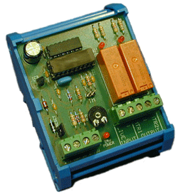
The MVC 010T Raise / Lower Controller is designed to control
an electric valve actuator with an operating time (from open to closed)
of 3.75 minutes or less.
The MVC 010T will open or close the valve in
proportion to the voltage change in the 0-10Vdc Input Signal.
The MVC 010T will control in a time proportional
manner, proportional to 0-10Vdc input.e.g. Input change by 2V then
output relay will be switched on for 45s.
To maintain actuator position the MVC 010T, will
drive the actuator closed for 4 minutes
Once every 24 hours, the MVC 010T will operate
Relay K1 (MTR1) for 4 minutes to ensure the valve returns to a known
state.
|

MVC 010T |
|
|
|
|
|
|
|
|
|
 |
|
|
|
|
Datasheet |
|
|
|
|
|
MTS 010
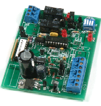
This module is intended for use with BMS controllers to convert an
analogue control output to a raise/lower, high/low or binary relay
output pair.
Applications include the control of raise/lower
valve and damper actuators, and pump changeover.
LEDs indicate correct operation and Hand/off/Auto
jumpers ease commissioning.
Low current draw from 0-10vdc controller output
means that the MTS 010 can work successfully with most DDC
controller. |

MTS 010 |
|
|
|
|
|
|
|
|
 |
 |
|
|
|
CE-cert. |
Datasheet |
|
|
|
|
|
Analog to Floating Point Output
The FAC allows an analog signal to control a floating point actuator.
FAC converts an analog signal into two relay
contact outputs (one increase/one decrease).
The FAC's isolated floating point output can be
controlled by any one of eight analog input signal ranges (jumper
selectable).
On a loss of power, the FAC's output relays will
be open, and no signal will be generated.
An LED indicates power to the FAC.
The output rate of change (nine ranges, in four
versions) is DIP switch selectable. In Version 4, the FAC relays stay on
at minimum and maximum positons.
Custom rates of change are available upon request.
|
Picture
not yet available |
|
|
Floating Point to Floating Point Out
The FPF allows a floating point signal of one rate of change
to be converted to a floating point signal of a different rate of change.
The FPF's isolated floating point output (two relay contact outputs, one
Increase or UP, the other Decrease or DOWN) can be controlled by a relay,
transistor or triac input, at 50 or 60 Hz.
On a loss in power, the FPF's relays will be open,
and no signal will be generated.
The actuator will remain at the last commanded position unless it is
"spring return". An LED indicates power to the FPF.
The FPF input and output rate of change are DIP
switch selectable.
Offered are four input versions (with 14 timing ranges) and three output
versions (with 9 timing ranges).
Custom rates of change are available upon request.
An auxiliary 24Vdc output will be supplied as the voltage source for a
dry contact pulse input signal. |
 |
|
|
|
|
|
|