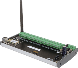
The RF-RX20 or RF-RX40 receiver collects
data from all other devices on the radio network, including measurements
from sensors, link quality for all links formed in the network, battery
levels for all battery powered devices, hours run for all devices and
the current status of all devices.
General
RF-RX
Information
Startguide
Datasheet
Note: Each receiver can support a maximum
of 16 ‘children’, which can consist of a maximum of 8 battery powered
nodes and 8 routers, or up to 16 routers if there are no battery powered
nodes.
Leaflet
on request
A USB socket is provided for connection to a PC
or laptop running the SonNet CMS software.
Technical Overview
Routers are used to route signals from battery
powered nodes and other routers to the receiver module, where the signal
strength of a direct path is not sufficient for reliable communications.
Data is transmitted back to the receiver at configurable time intervals,
or on a configurable change in measured value. Each sensor retains these
configurations if the battery becomes discharged or requires replacement.
The sensors, routers and receiver automatically
select which of the 16 transmission channels available gives the best
radio network performance, taking into account both signal strength and
interference levels from adjacent channels and equipment (such as Wi-Fi
etc.) The sensors and routers automatically find the best path back to
the receiver, which may be directly to the receiver or via “parent”
routers. NB Each router can support a maximum of 16 “children”, a
maximum of 8 of which can be battery powered “end devices” and a maximum
of which can be 8 routers. Consideration should be given on network
planning for redundancy in case of router failure or damage.
Installation
Remove all packaging from the receiver
Note the MAC address printed on the affixed
label and note where this MAC address is installed.
Mount the receiver in the required position
(this will have been determined during the site survey, (see the
quick start guide and manual for further details), taking care not
to site the receiver behind any obstruction likely to impede the
radio signal
Fix the receiver to the DIN rail
NB If the receiver is to be mounted in a
metal enclosure, it is essential that the aerial is mounted
externally. A 2m and 5m coaxial extension cable assembly is
available for this option.
Ensure, at a minimum, that all routers and
the receiver on the radio network are powered on, and allow about 15
minutes for the network to autocommission before attempting to read
values or make configuration changes.
Ensure the antenna is positioned in a
vertical alignment.
Observe correct polarity if using a 24Vdc
power supply.
To power on the unit, move the power switch
to the ON position.